Page 1 of 3
Question concerning rotary valve linkage modifications
Posted: Sun May 01, 2005 10:50 pm
by poomshanka
Apologies for the crude illustration here - not 100% anatomically correct, but I hope it gets the point across...

Above is an idea of what I might like to attempt on a rotary Willson 3050 CC. I'm having a problem with the valve paddles being too high on the horn, and was hoping that by re-jiggering the linkages in this fashion, it might make the horn a bit more "ergonomically friendly".
Aside from comfort, one additional improvement (for those who believe in it, anyway) is that the valves would all rotate the same way - back into the airstream.
What concerns me is how this would affect the valve action. Assuming the linkage rod material was suitably stiff, would the force still be translated into the valve pivoting mechanism straight-on, or would it cause some kind of oddball deflection/wear? How far off-axis could I get without running into problems?
Thanx...
...Dave
Posted: Sun May 01, 2005 11:00 pm
by TubaTodd
GREAT diagram!!!! What program did you use to draw it?
(To use a common "Iron Chef" phrase)
If my memory serves me correctly....I believe Matt Walters or another well known tuba construction expert recently chimed in during another topic and said that the direction of the valve rotation really doesn't make a big enough difference. I wish I knew which thread that was in.
As for the comfort, what ever floats your boat.

I like personally think the Marzan design (tilted valves) is the best ergonomical design that I have seen. It's very comfortable. I believe Yamaha borrowed part of that idea when they designed the 822 series.
I'm sorry I don't think I answered your specific questions.

Posted: Sun May 01, 2005 11:09 pm
by Will
I agree, great diagram.
But another solution could be to lengthen the first and second paddles and shorten the fourth, kind of like the curve of the paddles on a Miraphone but flipped. I pondered doing this to my 188 but chose to sell it and get a different horn more suited to me physically.
That may be a quicker and cheaper fix.
Posted: Sun May 01, 2005 11:17 pm
by poomshanka
TubaTodd wrote:GREAT diagram!!!! What program did you use to draw it?
Adobe Illustrator. That's actually how I pay my bills these days (along with Photoshop, Quark, InDesign, and a few others).
I've thought about the "Marzan" approach, but don't think I'd like this horn tilted at a sufficient angle to remedy the problem. That might alleviate the odd wrist angle issue, but my arm would still be farther up in the air than I like.
"Cost is no object", or, you know... I'm also interested in exploring some of the spendier options...
...Dave
Posted: Sun May 01, 2005 11:54 pm
by poomshanka
bloke wrote:Less surgery (assuming the factory linkage is satisfactory and quiet) might be to simply cut the spatulas (only) and rebraze them "offset" ...leaving everything else in place.
I've gotta drop these things a good 2-3", and don't think I could get that degree of offset with a paddle shift. There's another tuning slide running that far south that would facilitate relocating the linkage and its bracing, but only if the push rods had a jog in them.
If the axe wasn't the best rotary horn I've ever had in my sweaty palms, I'd have sent it back to Dave Fedderly for a refund. I've got a line in to Robb Stewart to see what he thinks as well...
...Dave
Posted: Mon May 02, 2005 12:06 am
by poomshanka
JCRaymo wrote:I was wondering if your 3050 has all 5 valves right hand operated or is the 5th valve left hand?
All five right. It's the second horn Willson made for Paul Krzywicki (the first one having a left-hand fifth valve).
I predict you'll be hearing a lot more about this horn in the future. I'm working on a couple "proof on concept" mods on this thing that'll have negligible impact on the manufacturing process, but a huge impact on the ergonomics. Now to get Switzerland to play ball...

...Dave
Posted: Mon May 02, 2005 2:04 pm
by poomshanka
harold wrote:This will undoubtedly alter the rotation of the bearing with resultant uneven wear.
I would worry about the torque changes that moving the linkages would create.
This is my main concern. Where it gets a little hazy for me is in the jog I've illustrated. If the linkage coming out of the paddle lever and into the rotor is straight, and the center section is what's angled, would the valve itself "know the difference"?
I tossed the "all valves rotate the same direction" out there just really as an aside ("for those who believe in it, anyway"), not an assertion that it would make an appreciable performance difference (a la lacquer vs. silver vs. unlacquered, heavy-walled mouthpieces vs. regular, et al). Even if it's a push performance-wise, by dropping the 3rd and 4th valve linkage posts down to the other side of the rotors, you'd get the mechanisms closer to the paddle levers and end up with less deflection on the jog.
It's really the jog I'm curious about.
Thanx!!
...Dave
Posted: Mon May 02, 2005 3:10 pm
by Lee Stofer
Dave,
I do not want to sound discouraging, but my work with rotors leads me to believe that a linkage system like that would not work well at all. The wear factor would be significant, but the worst drawback would be the long, non-precise feel of the valve action, if they worked at all.
One of the most important factors in valve action is maintaining as close to an absolute straight-line action as possible. The linkage does, "know the difference", and you will, too. Reversing the direction of travel on the 3rd and 4th valves has not shown me enough proof of anything to recommend it as either good or bad.
Since you do find the ergonomics of this instrument to be difficult, I'd suggest trying using a stand, so the instrument can be lowered to where you have a comfortable hand position. It would be much less expensive than having the entire valveset relocated on the instrument. I wish I could offer a brilliant solution, but just don't think there is a quick or easy fix.
Posted: Mon May 02, 2005 3:36 pm
by poomshanka
Lee Stofer wrote:Since you do find the ergonomics of this instrument to be difficult, I'd suggest trying using a stand, so the instrument can be lowered to where you have a comfortable hand position. It would be much less expensive than having the entire valveset relocated on the instrument. I wish I could offer a brilliant solution, but just don't think there is a quick or easy fix.
Lee...
Thanx for the input. I'm actually using a Baltimore Brass stand and Roc-n-Soc drum throne right now to help tame this thing, but the problem with dropping the horn (and thus the valve paddles) is that the leadpipe goes along with it. So the valve paddles are either too high, or the leadpipe too low.
The leadpipe, unfortunately, doesn't have any wiggle room in it. Under normal circumstances, I could probably just have it raised. Problem is it's virtually a straight shot from the valves around the bell, and it ends awfully close to the bell at that.
Frustrating...
...Dave
Re: Question concerning rotary valve linkage modifications
Posted: Mon May 02, 2005 7:20 pm
by Rick Denney
poomshanka wrote:Above is an idea of what I might like to attempt on a rotary Willson 3050 CC. I'm having a problem with the valve paddles being too high on the horn, and was hoping that by re-jiggering the linkages in this fashion, it might make the horn a bit more "ergonomically friendly".
I've glanced through some of the responses, but none really describe my issues with this approach.
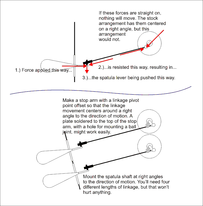
1.) when you change the angle of the linkage significantly, you change the mechanics of the linkage. See the top part of the diagram. This will apply a lateral force on the linkage, which will increase wear and make it feel spongy. This problem is not solved (sorry, Joe) with Bloke's suggestion, though his suggestion does solve my second problem. You can only fix this by making the spatula shaft go at right angle to the direction of motion, so that it pushes right along the length of the linkage, as shown in the bottom part of the diagram.
2.) the pivot on the stop arm needs to center on right angles to the direction of motion, as shown on the top part of the diagram. You can do that with a plate on the stop arm that clocks the pivot point around as per the bottom part of the diagram. That will leave the stop pin and the stop plate in the same place.
With my suggested approach, all you'll have to have made from scratch is the bar stock that mounts the spatula shaft, and it's attachment points on the tuba.
Rick "who uses Corel Draw, heh, heh" Denney
Posted: Mon May 02, 2005 7:32 pm
by MaryAnn
bloke wrote: You might notice (below) that both my rotor and piston operating surfaces are slippery"
Well on my tubas I just wonk away as the paddles are so big and the finger action is up-down, but on my horn....even with my small scale horn I have to reach "all the way" to hit the thumb valve and the paddles at the same time. I've ended up hitting the
ends of the valves with my fingertips, a la violin, and it works fine. Never saw anybody else with that close a tolerance hit-or-miss yet, though.
MA
Posted: Mon May 02, 2005 7:49 pm
by Chuck(G)
If yoiu've got to shift things down 2-3", then none of these illustrations is even remotely to scale. If I read you right, you want the new 1st valve spatula where the 3rd valve spatula now resides.
Do I have this right?
(Thinking that that's a heckuva lot of shifting...)
Posted: Mon May 02, 2005 7:58 pm
by cjk
If the honorable Mr. Art Hovey can come up with this (
EXTREMELY impressive btw), I'm pretty sure somebody could come up with something that will address your problem. However, it'd be a lot cheaper to just learn to play the horn as is.


Posted: Mon May 02, 2005 8:25 pm
by Rick Denney
bloke wrote:Though it wasn't drawn correctly (' actually on the wrong side of the carriage bar...' used the existing pic and altered it), I really don't see any reason why the suggestion I made (9th post in the thread) wouldn't work. The same sort of mechanism is used on (literally) millions of flutes...Mash the buttons here - trill key pads go up and down over there...
Because people mash the buttons on tubas with quite a bit more force, and over quite a bit more distance, than they do on flutes. The result is that the linkage has to be stiff enough not to fatigue or feel mushy, and an inch or two of offset is quite a lot compared to less than half an inch.
And thumb linkages don't get the same pounding as finger linkages, for the simple reason that the thumb rotates around the thumb ring the last joint is doing all the work. The fingers rotate around the knuckle, which attaches to much bigger muscles.
Rick "who thinks an angled arrangement would actually be easier to implement" Denney
valve linkage change
Posted: Mon May 02, 2005 8:52 pm
by tubamirum
So, any time a lever is pressed and a valve rotates there is going to be wear. How much do you use the horn? Will you need to replate in 1, 5, 10 ,20 years? Just do it and don't worry.
Posted: Mon May 02, 2005 11:28 pm
by poomshanka
OK, enough with the Illustrator vs. Corel Draw monkey business - time to push some pixels!!!


Here's what it might look like, real-world. Slight jogs on the 3rd and 4th valves, more extreme on 1 and 2. Of course, the fifth valve linkage will have to be re-done, and the 4th valve tuning slide will need to be re-routed to accomodate that modification. There's another ergonomic benefit to that mod that's beyond the scope of this current discussion.
I don't favor any type of Marzan-esque approach that would rotate the angle of attack on the paddles. Of course, if it could be done in a way that kept the ends of the paddles in their current orientation (just down a ways), I'd be open to that.
And for you pixels pushers with broadband access who'd like to take a crack at the hi-rez layered Photoshop file...
http://www.daveamason.com/tuba/willson_modified.sit
Note that this is the full monty (26MB), and I downsampled the before and after JPEGs to 600 X 800 before I posted them.
Thanx for all the input on this post - I really appreciate it!
...Dave
Posted: Tue May 03, 2005 12:38 am
by dave
The pics are nice and clear. I don't think it is going to work well enough for you to be happy. The first valve linkage will be applying force along the angle between the spatula and the valve stem, i.e. not in the direction that the rotor wants to move when at rest. Thats not a recipe for light action.
Go back and study Bloke's SUPERB Gronitz linkage. The reason this works is that it has an extra FIXED bearing that the linkage rotates around (next to the first valve) That way all the force is applied in the same direction as the linkage, from paddle to fixed bearing, and from fixed bearing to the valve. If you did something similar you can move the paddles wherever you want them.
-Dave
Posted: Tue May 03, 2005 12:56 am
by Chuck(G)
bloke wrote:very nice graphics...
Yeah, I still think you could solve it with either offset spatulas or offset T-joints, rather than having to go with diagonal push rods.
The second valve extension might be a little shorter than optimal, but yeah, I like your idea.
Of course, there's always
cables and pulleys

Posted: Tue May 03, 2005 6:46 am
by Joe Baker
Why not set up valves 1 & 2 with bell-cranks, so that the valve is actually pulled into the activated position instead of pushed? Like this:

Of course I defer to the guys that actually do this stuff for a living.
____________________________________
Joe Baker, who is no expert in tuba modification, but can improvise mechanically with the best of 'em!
Posted: Tue May 03, 2005 10:27 am
by Rick Denney
bloke wrote:oh...sorry...I was thinking of someone like
me doing the job - not just anyone.


I should have said it differently: People use a lot more force than is necessary to mash the buttons, particularly on the first three valves. Thus, even if the valves are built and tweaked to Blokian standards, with springs to match, people might still pound them, just like I do on this flimsy Dell keyboard.
I would think with your design the spatula lever would need to be stiffened, and the long pin needed to make the offset would need to be braced somehow. Otherwise, I think it will fatigue.
Of course, if the stops were at the paddles instead of the rotor as they would be if this had been designed by a machine designer, then the linkage could be much lighter.
Rick "who may someday make a rotary linkage assembly with proper design just for fun" Denney