Forgive my ignorance/lack of correct terminology...
Is the 'action' (mechanism?) of a rotary valve fixed?
If I wanted to move the action of a rotary valve by 90 degrees but keep the plumbing the same is that possible?
ie: Keep the housing as-is but change the position of the mechanism-side (with the bumpers, screws etc) to allow a different lever design.
In the highly likely event that this makes no sense, could anyone show me/explain how a rotary valve is assembled!? Easy right?
Thanks for any help here...
MP
Rotor Action Adjustment
-
Peach

- 4 valves

- Posts: 701
- Joined: Thu Mar 17, 2005 8:42 am
- Location: London, UK
Rotor Action Adjustment
Peach
-
Peach
- 4 valves
- Posts: 701
- Joined: Thu Mar 17, 2005 8:42 am
- Location: London, UK
Thanks for biting but if I'm seeing right, the action of the rotors themselves still moves across the horn like they did leaving the factory...
I'm talking about switching the action through 90deg to making the action up-and-down - 'in-line' with the airflow. This is regarding a 5th valve by the way.
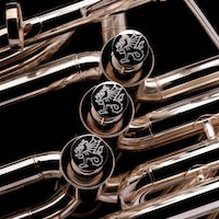
Here's something like what I want - with the action up-and-down the line of the horn:

Currently the action is across the horn. Do I need to buy a new valve (!) or think of a new mechanism design, or can I switch the action??
Really hoping this makes sense!
I'm talking about switching the action through 90deg to making the action up-and-down - 'in-line' with the airflow. This is regarding a 5th valve by the way.
Here's something like what I want - with the action up-and-down the line of the horn:
Currently the action is across the horn. Do I need to buy a new valve (!) or think of a new mechanism design, or can I switch the action??
Really hoping this makes sense!
Peach
-
Chuck(G)

- 6 valves

- Posts: 5679
- Joined: Fri Mar 19, 2004 12:48 am
- Location: Not out of the woods yet.
- Contact:

-
Dean E

- 5 valves

- Posts: 1019
- Joined: Fri Mar 19, 2004 10:36 am
- Location: Northern Virginia, USA
- Contact:
Re: Rotor Action Adjustment
It can be done, Peach, but why? Seriously, if you have some ideas, please let me know.Peach wrote:Forgive my ignorance/lack of correct terminology...
Is the 'action' (mechanism?) of a rotary valve fixed?
If I wanted to move the action of a rotary valve by 90 degrees but keep the plumbing the same is that possible?
ie: Keep the housing as-is but change the position of the mechanism-side (with the bumpers, screws etc) to allow a different lever design. . . . .
viewtopic.php?t=16359&highlight=reverse+rotor
Dean E
[S]tudy politics and war, that our sons may have liberty to study mathematics and philosophy. Our sons ought to study mathematics and philosophy . . . in order to give their children a right to study painting, poetry [and] music. . . . John Adams (1780)
[S]tudy politics and war, that our sons may have liberty to study mathematics and philosophy. Our sons ought to study mathematics and philosophy . . . in order to give their children a right to study painting, poetry [and] music. . . . John Adams (1780)
-
iiipopes

- Utility Infielder
- Posts: 8595
- Joined: Tue Sep 06, 2005 1:10 am
If I understand you correctly, the "top" cap of the rotor housing through which the rotor spindle goes and has the rotor stops on it is usually soldered or formed as part of the housing. So in general, no, you can't rotate the top of the housing separately for a different linkage geometry. If your ferrules/knuckles are all at the same angle coming out of all four ports of the rotor casing, you might be able to unsolder the entire housing, turn it 90 degrees, resolder it, then work your linkage so the rotor works "backwards," but that is quite a job that probably isn't worth the cost in time or money. It's probably best to try to figure out a different linkage/lever instead.
Jupiter JTU1110
"Real" Conn 36K
"Real" Conn 36K
-
Wyvern
- Wessex Tubas

- Posts: 5033
- Joined: Fri Sep 01, 2006 7:00 pm
- Location: Hampshire, England when not travelling around the world on Wessex business
- Contact:
-
windshieldbug

- Once got the "hand" as a cue

- Posts: 11518
- Joined: Tue Mar 01, 2005 4:41 pm
- Location: 8vb
-
Chuck(G)
- 6 valves
- Posts: 5679
- Joined: Fri Mar 19, 2004 12:48 am
- Location: Not out of the woods yet.
- Contact:
If I understand my geometry right, Peach, you want to rotate the linkage assembly through one-quarter of a circle, not one-half, as if one were changing the rotor direction.
A bell crank, or, as Joe suggested, modifying the stop arm so that there's an attachment point 90 degrees from the stop pin--it can be done.
I've changed over a couple of string-linkage horns to uniball by brazing attachment points to the stop arms 180 degrees from the stop arm pin. This meant that I didn't have to move the stop block at all.
I don't know if that's what you have in mind, however.
-
Peach
- 4 valves
- Posts: 701
- Joined: Thu Mar 17, 2005 8:42 am
- Location: London, UK
Award for "Most vague post 2007" goes to...
OK, this has nothing to do with air-flow and everything to do with the plain mechanics of operating the valve. For the record I don't care which way a valve moves internally - up & down/round & round etc etc.
I think Chuck and Joe had it right in their respective takes...
I'll try to explain.
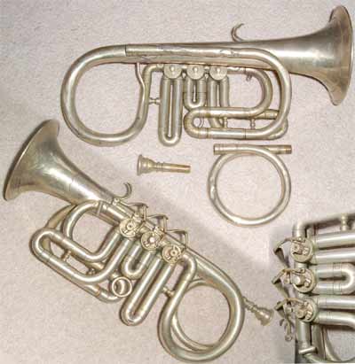
At the moment the 5th valve on my C looks a lot like this:

Same 5th slide setup too - flat and up the side of the bell.
The 5th lever is routed the same too only it's solid - to get the movement across the horn to move the valve (rather than the up-down version on the Gronitz).
For whatever reason(s) the 5th valve is switching to dependant and so the mechanism needs to change (I never really liked it as it is to be honest).
Sounds like I'm best to leave the valve alone and work out a new lever design to go with what's there...
Apologies for confusing folks!
Best,
MP
OK, this has nothing to do with air-flow and everything to do with the plain mechanics of operating the valve. For the record I don't care which way a valve moves internally - up & down/round & round etc etc.
I think Chuck and Joe had it right in their respective takes...
I'll try to explain.
At the moment the 5th valve on my C looks a lot like this:
Same 5th slide setup too - flat and up the side of the bell.
The 5th lever is routed the same too only it's solid - to get the movement across the horn to move the valve (rather than the up-down version on the Gronitz).
For whatever reason(s) the 5th valve is switching to dependant and so the mechanism needs to change (I never really liked it as it is to be honest).
Sounds like I'm best to leave the valve alone and work out a new lever design to go with what's there...
Apologies for confusing folks!
Best,
MP
Peach